Removing the Splash Pan

The Splash Pan can be removed from the Omni Spindle Housing quite easily.

Remove the Platen and Spindle first.

Once the Platen and Spindle have been removed, look under the Splash Pan to locate the attachment screws. Using a 3/32″ Allen key loosen these screws.

Omni Splash Pan attachment screws.

Once loosened, the Splash Pan will lift off the Spindle Housing easily. Unless it’s corroded into place, in which case a couple light shots of WD40 and gentle tapping should loosen it.

More information about corrosion in the discussion and photos about Omni Design Flaws section.

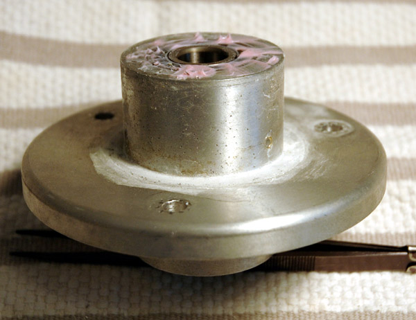
Here’s a photo of the Splash Pan bottom once it has been removed from the Spindle Housing. Notice the signs of corrosion in the collar that surrounds the Spindle Housing.

Splash Pan Bottom view

Posted in Splash Pan | Tagged , , , , , | Leave a comment

Removing the Omni Spindle Housing

First remove the Platen and Spindle. Removing the Splash Pan will make your job easier, though the photos here show removing the Spindle Housing with the Splash Pan still attached.

The Spindle Housing is a machined block of aluminum which holds a couple of sealed bearings. The Platen and Spindle assembly slide into these bearings.

The Spindle Housing is attached to the Base Plate by three hold-down bolts. Under the Spindle Housing next to the hold-down bolt holes are three set screws which adjust the Platen Tilt alignment.

Close-up photo of Omni Spindle Housing hold-down bolts

Carefully use a 7/16″ wrench to loosen these Spindle Housing hold-down bolts. I loosened them off 1/4 turn each, going around to all 3 in turn until they were loose enough to remove by hand.

This space is cramped so take your time and be careful.

Once the bolts are removed the whole Spindle Housing and Splash Pan are free to be lifted out.

Here is a bottom view of the removed Spindle Housing with Splash Pan attached.

Spindle Housing and Splash Pan bottom.

A close-up of the Spindle Housing bottom. Hard to see here but there is evidence of water and corrosion starting on the Spindle Housing. It’s seen the clearest as the rust-colored are around the bottom bolt hole.

Spindle Housing bottom close-up

And here is a close-up of the Spindle Housing assembly removed from the Splash Pan. Note the dull appearance of this part with the corrosion pits and water leakage stains. The pink goop on the bearings is some sort of grease applied at the Jersey Instruments factory. Please visit the Omni Design Flaws section for more discussion.

Omni Spindle Housing Close-up Showing Corrosion

This is what the Omni Base Plate looked like when I removed my Spindle Housing. Note the rubber o-rings as well as the obvious water-staining.

Corrosion and Water Marks under Spindle Housing.

And this is a close-up shot of where the Spindle Housing sits. Notice the three set screws for adjusting the Platen Tilt, as well as the rust and corrosion marks.

Close-up of Omni Base Plate corrosion under Spindle Housing

For more detailed photos and discussion visit the Omni Design Flaws section.

Posted in Spindle Housing | Tagged , , , , , | Leave a comment

Removing the Motor, Controller Box and Drip Tank Stand

Removing the Omni Motor, Controller Box and Drip Tank Stand is rather simple.

You need to have completed the Disassembly First Steps and Omni Bottom and Pulley Assembly steps first.

Spin the Motor Pulley so you can locate the set screw as shown below. Using a 3/32″ Allen screw, loosen the set screw and the pulley should come off the Motor easily.

Omni Motor Pulley set screw closeup.

Now locate the Control Box and Drip Tank Stand attachment bolts. For some reason Jersey Instruments has used a mix of Metric and Imperial fasteners and measurements to construct the Omni. These two bolts require the use of a 4 mm Metric Allen key to remove. They are both rather tight so be careful when loosening them. Once they are loose, hold the Control Box and Drip Tank Stand while removing the bolts.

Controller Box and Drip Tank Stand attachment bolts

Don’t forget to unscrew the last Encoder cable hold-down on the base near the Swing Arm attachment.

Setting the Omni back upright, use a Phillips screwdriver to loosen and remove the three screws holding the Motor to the Base Plate.

Carefully set aside the Motor and Controller Box where it will not be damaged. Make sure you don’t lose any of the bolts and screws either!

The following photo shows the Base Plate after all components have been removed. Go here for instructions on how removing the Spindle Housing.

The Omni Base Plate laid bare

Posted in Motor & Controller | Tagged , , | Leave a comment

Omni Mast Not Aligned

Initially I had made the assumption that the major components of the Omni – such as the Base Plate, Swing Arm and Mast – would not require any adjustment or modifications.

However as I progressed in trying to align my machine I came to the conclusion that I could trust nothing and set about measuring and testing each component.

The most perplexing problem was that as I swing the quill and dop across the lap, the tip of the dop would travel in an arc over the lap. And that arc would not be the same height depending on what position the swing arm was in.

I don’t have any photos to demonstrate the problem so you’ll have to visualize this with my little sketches.

Imagine you are looking across the lap at the end of the dop. Adjust the dop so it is just barely touching the surface of your lap at the 6 o’clock position. Now swing the dop across the lap to the far side. When I did this, my dop travelled in an arc with the highest point somewhere near the hold-down screw in the middle. But the dop did not touch the lap at the far side!

Dop travelling in an arc over the lap.

After puzzling over this for a while, I tried moving the swing arm out and tested on different parts of the lap – still getting the arc but not the same amount of arc.

I realized that this indicated that the mast was not true – that depending on what direction the mast was facing, the dop and quill would move in a different arc. The sketch below will give you an idea what I’m talking about. The dop will follow the edge of the disk, so you can see how the arc the dop travels will change as the orientation of the mast changes.

Visualizing the dop travel arc

So the first thing I needed to do was Align the Mast. This was complicated significantly upon my discovery that the Base Plate is warped, leaving me nothing reliable to measure the Mast alignment against.

By the way, if your Mast is leaning the opposite way (towards the lap), the arc the dop tip traces will look like this:

Dop travelling in an arc over the lap.

Posted in Mast Alignment | Tagged , , | Leave a comment

Omni Platen Vertical Runout AKA “Platen Hop”

My platen – the flat part the lap rests upon – is not flat. This means as you cut a stone, the lap has high and low spots as it rotates which continually tap-tap-tap on the stone. I had a Topaz I was working on cleave which I attribute to the stone continuously being hit by the high spot. The faster you run the machine, the more this causes vibration and a jack-hammer effect on your stone and faceting head. Not what you want on a precision machine.

In machinist parlance, this hop is called “vertical runout”. Using a 1/1000th inch dial indicator, I tested my platen near the edge, approximately 5.5″ from the center. An acceptable runout would be 0.001″ (1 thousandths of an inch) or less, and I know of several fellow faceters locally whose machines (not Omni) came from the factory with less than 0.001″ runout.

Originally I complained that my vertical runout was 0.0015″ (1-1/2 thousandths of an inch) which was slightly annoying. Foolish me.

My vertical runout is now 0.007″, almost FIVE TIMES WORSE than what it was before I sent it back to the factory. I repeat: This is *after* it came back from the factory for alignment.

Here are some photos demonstrating the problem:

Omni Platen Vertical Runout Image 1

Dial Indicator zeroed at the high point.

Omni Platen Vertical Runout Image 2

Turned 90 degrees clockwise… 0.0025″ difference…

Omni Platen Vertical Runout Image 3

Low point on the Platen. Only out by 0.007″!

Omni Platen Vertical Runout Image 4

The Platen at 9 o’clock position. Out by 0.005″.

These measurements were taken at about 5.5″ from the center of the platen.

When I emailed the well-known owner of Faceters.com about this, here’s the response (typos are his):
“You are kidding me right? .007? There is not a machine out there that will get any better. Facette and UT on brand new machines send them out with those numbers. Why dfon’t you just go cut stones…?
Jeff”

I call BULLSHIT.

Quoting from UltraTec’s page:
THE PLATEN – This critical subassembly (L) which holds the lap provides exceptional accuracy–.0003 inch maximum vertical runout.

For the record – UT publishes their platen runout here:
http://www.ultratec-facet.com/V2Base.htm

So Ultratech machines their platens (4″ diameter) to 23x tighter specs than my Omni. If any Facetron or Fac-ette owners care to chip in their factory-spec platen runout numbers I’d be happy to post them for comparison. I’m not interested in modded machines, only factory-shipped specifications.

Posted in Platen Hop | Tagged , , | 1 Comment

Platen Tilt Alignment Problem

To illustrate the Platen Tilt alignment problem I have a couple of photos. There is an angular slope to the platen with the low point at the control box side and high point at the user side.

With a dop resting on the lap and the head in a 40 degree position, there is 0.2 degrees of difference in the angle read-out from the 1 o’clock position (closest to the control box) to the 6 o’clock position (closest to the operator).

This is *after* I sent the machine back to the factory to have it serviced and was told by the owner “Upon reassemble, the master plate calibration was within (+-) .05 degrees, well within acceptable limits“.

As you can see for yourself, this is not the case. This is not acceptable – what is means is that when you sweep the stone from edge to center, your stone will no longer contact the lap at the center. It also means that if you move the swing arm to another position, the angle of the lap to your facet changes, meaning that your meets will not meet and you will have to use a lot of cheating to get the facet back.

If you’re trying to cut a large or rectangular stone, good luck.

Omni Platen Tilt Alignment Problem Image 1

In this picture the height has been adjusted so the stone is barely contacting the lap (a ceramic lap that I know is flat). The swing arm is in as close to the machine as possible without contacting the rubber around the splash pan edge.

Omni Platen Tilt Alignment Problem Image 2

Here the stone is in full contact with the lap. All I did was move the swing arm out and bring the stone to the 6 o’clock position. No height or angle adjustments were made.

This complaint is a common refrain amongst those Omni owners I’ve had contact with. It’s pretty much universal both in the nature of the complaint as well as the degree the alignment is out.

Posted in Platen Tilt | Tagged , , | 1 Comment

Removing the Spindle and Platen

First remove the bottom drive belt cover, drive belts and Pulley from the Spindle.

Omni Spindle Bottom End

At this point all you need to do is get a wooden dowel or block of wood and carefully tap/press against the bottom end of the spindle, shown here. It is a slight friction-fit with the bearings but will easily slide up through the bearings. If you are having difficulty a quick spray of WD40 may help.

Have an assistant holding the Platen and Spindle so that it doesn’t drop and damage itself or the machine.

Once the Spindle has moved up a bit, you can put the machine upright and grasp the platen on either side. Carefully pull it from the bearings having your assistant hold the Omni base steady. It will be much easier to tap the spindle free using a dowel however.

Omni Spindle And Platen

This is what the Spindle and Pulley look like when removed from the Spindle Housing. In this picture I have it resting on the machine base after I removed the Spindle Housing and Splash pan – which is not necessary to get the Spindle and Platen free.

Note that the Platen is a press-fit Aluminum plate on a steel spindle. You can also see punch marks between the black marker lines on the shaft. These punch marks are apparently to help the shaft fit more snugly into the bearings.

I sent this off to a machinist to have the Platen spun and levelled to try to eliminate the hop. I also asked the machinist to reduce the diameter of the Platen from the current 5.75″ to 4″. This will allow me to mount a 6″ saw blade on the platen to slice larger rough.

The results of the modifications can be seen here:

Modified Platen

This is what the machine looks like without the Platen and Spindle in place.

Omni with Platen and Spindle Removed

Do you see a rather severe design flaw here? More detailed photos and discussion are on the Omni Design Flaws pages

Posted in Platen and Spindle | Tagged , , , | Leave a comment

Omni-E Alignment Problems – Many Different Issues

In my quest to adjust the alignment of my Omni, I discovered that there were a few different issues at hand.

  1. The Mast is not perpendicular to the Base Plate
  2. The Base Plate is not flat
  3. The Platen is not perpendicular to the Mast
  4. The Swing Arm has flex/play in it
  5. The Platen has excessive vertical runout
  6. My Spindle appears to be bent

Because at the time I started my alignment I did not know about issues 1, 2, and 6 decided the best thing to do would be get my Platen machined to take out the hop. In order to do that I needed to remove the Platen and Spindle from the machine.

After having the Platen machined (and made smaller) I discovered that there still was a significant Platen hop of 0.0035″ (3-1/2 thousandths of an inch). Half of what it originally was, but much more than the 0.001″ tolerance the Platen was just machined to. After a bit of monkeying around I came to the conclusion that the Spindle may be slightly bent near the top, just under where the Platen sits.

Update: the Spindle was not bent. The Spindle diameter was too narrow to fit snugly into the bearings of the Spindle Housing which meant that it wasn’t held tightly and wobbled when spun.

I set about trying to align the Platen to the Faceting Head by putting a dop in the Quill and adjusting the angle and height of the head so it barely touched the Platen above one of the Adjustment Bolts. Visit the Omni Platen Alignment page.

After thinking I had the Platen aligned, I tried cutting a test stone and realized that the Mast was not perpendicular to the Platen and I set about trying to figure out how to align the Mast. It was then I discovered that the Base Plate was not flat. And after some thinking I came across what appears to be a workable solution to that. Visit the Omni Mast Alignment page.

All told, I have spent about 2 weeks on and off getting parts machined and probably 5-6 hours actually getting parts aligned to each other. At this point I’m reasonably happy with my work but still have some ideas left to try.

I should add that after all these alignments (and documenting them for this site) I haven’t had a chance to cut a rectangular stone to see if the problems I was having are reduced. I’ll post my results of that when I get a chance.

Posted in Omni Alignment Problems | Tagged , , , , | Leave a comment