The Omni Transfer Jig is Sloppy

There have been several people writing about the Omni Transfer Jig not being accurate and introducing transfer alignment errors. I too am experiencing these problems, but I have been able to isolate the cause and reduce its effects during transfer.

Look at these photos of the Transfer Jig and you will see that the sliding block is only constrained in one dimension, and that there is significant play in the block even when the single adjustment screw is tightened. In these pictures I’ve done my best to tighen everything so there is as little play as possible, but the mis-alignment that you can see was caused by merely touching the top of the sliding block.

Omni Transfer Jig front view

Omni Transfer Jig Alignment 1

Omni Transfer Jig Alignment 2

To mitigate this problem, I am careful to press down on the top of the sliding transfer block near the dop end. And since I use glue rather than wax, I don’t have to worry about thermal expansion.

If you examine the rest of the Transfer Jig photos you can see how the sliding block is only being pulled against the back part of the transfer rail, not against the bottom. You’ll also note that neither the rail nor the blocks have been machined to be accurate against each other – they appear to be stock material that has been cut and anodized.

Omni Transfer Jig angled view

Omni Transfer Jig view along back

Omni Transfer Jig bottom view

While it may be possible to modify the jig to work better, I will be shopping around for a Transfer Jig of a proven design. I have been told that the Polymetric Transfer Jig may work with a slight modification, though it will not be keyed.

Posted in Omni Quality?, Transfer Jig | Tagged , | 6 Comments

Omni Swing Arm Flex

As detailed in the Swing Arm Disassembly page, the Omni Swing Arm flexes when you handle the Faceting Head.

This flex can be reduced but not eliminated by tightening the Swing Arm mounting nut underneath the Swing Arm. However tightning it does not eliminate all of the flex and can make it very difficult to move the Swing Arm.

As these photos show, the Omni relies upon two plastic disks to act as a bearing between the Swing Arm and the Base Plate. I believe the flex is inherent to using a compressible plastic for this bearing.

Closeup of the Swing Arm Plastic Bearings

Omni Swing Arm Plastic Bearing

My plan is to replace the plastic disks with brass sheeting of the same thickness. This will still provide an incompressible bearing which should resolve this issue. I will post photos of my modifications in the Omni Modifications section.

I have a report and photos from one Omni owner that his Swing Arm had a sheet of roughly-cut sheet rubber (similar to an inner tube) and a sheet of plastic as a bearing. Obviously he had significant Swing Arm flexing problems. He replaced these with sheet copper and is happier with the results.

Posted in Swing Arm Flex | Tagged , , , | Leave a comment

Omni Swing Arm and Mast Disassembly

Removing the Swing Arm and Mast from the Omni Faceting Machine is a relatively easy and straight-forward process.

Please ensure you have completed the Omni Disassembly First Steps before proceding.

Removing the Mast

Tip the machine back so you can access the nut on the bottom.

Locate the bolt holding the Mast to the Swing Arm. Using a 3/16″ Allen key, remove this bolt while holding the Mast so it doesn’t fall when the bolt is removed. In this photo you can see an ink mark I used when aligning the mast.

Closeup of Mast bolt

This is how the Mast is attached to the Swing Arm. Notice the brass bushing here. It’s not on very tightly and can be removed by hand without force. The second photo shows the poor machining done on this piece – which might explain why my Mast isn’t perpendicular.

Omni Mast Support and Bolt

Omni Mast Support Machining Quality Close-up

Removing the Swing Arm

Locate the nut underneath the Swing Arm plate. Use a wrench to loosen and remove this nut, holding the Swing Arm plate so it doesn’t fall and damage something.

Omni Swing Arm Nut

The Swing Arm plate should slide off the support easily. The brass Swing Arm Mount will be left. To remove this, set the Omni back upright. Use a wrench to remove the bolt holding the Swing Arm Mount.

Omni Swing Arm Mount

Here’s what is on my Omni between the Swing Arm and the Base Plate. These plastic disks act as a bushing between the two parts.

Closeup of the Swing Arm Plastic Bushings

Omni Swing Arm Plastic Bushing

I found that my Swing Arm had flex, even after I tightened the nut to the point where the Swing Arm was very difficult to move. I believe that this flex is inherent to using plastic disks as bushings. You can read more about this in the Omni Design Flaws section.

Here are exploded views of the Swing Arm components. The second photo shows the Swing Arm Bearing that fits over the Swing Arm Mount and is held in place on the top side by a split ring.

Omni Swing Arm Exploded View

Omni Swing Arm Bearing

I am going to replace the plastic disks with ones cut from thin brass sheeting of the same thickness to see if this creates a sturdier structure. Once I do this I will post photos in the Omni Modifications section.

You can remove the Swing Arm Mount by using a 7/16″ wrench. What you’re left with is shown below.

Omni Swing Arm Mount

Omni Base Plate Swing Arm Mounting Hole

Posted in Swing Arm/Mast | Tagged , , , | Leave a comment

What Does the Omni Warranty Actually Cover?

According to the Faceters.com review of the Omni, the Omni comes with a Lifetime Warantee on Parts and 1 Year Warranty on Electronics (text bolded by me for emphasis):
“Parts and service are one of the main considerations that you should think about when you are buying a new or used faceting machine. OMNI is warranteed for life time on mechanical parts and 1 year for electronics.

I see no such warranty stated anywhere on the invoice I received, the Jersey Instruments Website, or on the Faceters.com page where he sells the Omni.

What is the Official Warranty on the Omni?

According to the user manual that came with my Omni, it is:

“(36) WARRANTIES. We will correct any mechanical fault detrimental to the operation of the machine for which the manufacturer is responsible.
Motor: – Manufacturer’s warranty is twelve months from date of purchase of the machine.
Control: – Same as motor”

When I sent my machine back to the owner of Jersey Instruments for servicing to correct my alignment problems, he shipped it back to me and charged me $235 for the work and shipping. His email summary stated:

“There was evidence that at some point in this machines past, the spindle bearings were flooded. I will enclose one of the bearings for you. Your machine was restored to like new condition. New spindle bearings were installed. Two upgrades were installed. The machine was re-calibrated and cleaned.”

Never mind that the Omni was not returned in “like new condition”, unless all Omnis are shipped out of alignment and with poorly-machined parts.

I emailed him to ask what the “upgrades” were but he didn’t reply. I now know that one of the “upgrades” were to replace the ball bearing at the top of the mast (which the fine height adjustment sits on) with a larger one.

My questions are:

Given what I’ve documented in the Omni Design Flaws section, isn’t a flooded bearing a warranty issue?

Since the Omni has a design flaw that means *EVERYONE* who owns this model WILL flood their bearings, isn’t this a “mechanical fault detrimental to the operation of the machine for which the manufacturer is responsible”?

If the manufacturer isn’t responsible for a design flaw that will damage the machine, is the user at fault for doing nothing more than utilizing the machine in a fashion it is marketed and sold for?

Is this the sort of warranty support you expect from a manufacturer?

Posted in Omni Warranty | Tagged , , , | Leave a comment

The Omni Model Reviewed by Faceters.com Isn’t the One Shipping

According to the Faceters.com review of the Omni faceting machine:
“The OMNI machine is well designed and it is obvious when I cut on the machine that this design has evolved over a long period of time… In conclusion, the OMNI faceting machine one of the best quality and design in it’s price range.”

Look closely at the photos in this review. The machine in the photos is different than the Omni-E that is currently shipping. I noticed several obvious changes to the design, including but not limited to:

  • Angle readout is only 1/10 degree but the pictured machine is 1/100
  • Angle adjustment knob and locking mechanism has changed (notice the dumbell lever on the picture in the article)
  • Current dops are keyed 45 degree angle slice from the back, not a flat
  • Current dops are brass, not steel
  • Swing arm pivot mount appears quite different (large silver disk on the bottom)
  • Transfer fixture is not the same. The one shown appears to be a single piece of metal machined as one part without moving blocks

I believe that the machine reviewed is fundamentally different from the currently-shipping model. It appears that the reviewed model was closer to the original Laurie Hall Australian design which has now been changed.

I am not convinced that the well-known owner of Faceters.com would write the same review if he used the currently-shipping Omni-E for any length of time.

For the record: I contacted Laurie Hall to get some assistance with adjusting my Omni. He was firm but polite in his response – that the design was sold to the owner of Jersey Instruments and Laurie co-miserates with us, but he is both powerless to affect any change and blameless for the implementation of the Omni Faceting Machine. He added that he was disappointed in the design changes made to the Omni as he knew they would introduce problems. Because the Omni is built and sold by Jersey Instruments, he can not provide any support.

The Hall Faceting machine is still being manufactured in Australia by UNAMIT. You can read about it at the Astro-Tel website.

Posted in Omni Quality? | Tagged , , , | Leave a comment

Flooded Bearings a Fact of Omni Use

I have been contacted by several different Omni-E Faceting Machine owners. All of us have experienced water leaks and bearing problems on our machines, and those of us who have sent them back to the Jersey Instruments factory for repair have been told that we have flooded our bearings.

The owner of Jersey Instruments considers this owner abuse of the machine and charges for any repair work related to replacing the bearings.

As you will see from the following photos, I disagree completely. Due to a significant design flaw in the Omni Faceting Machine, I expect *EVERYONE* to have flooded bearings sooner or later. You are free to draw your own conclusions.

Please look carefully at this photo and tell me what your first thoughts are. I have cut 3 stones since getting it back from Jersey Instruments.

You are looking at the splash pan with the Spindle and Platen assembly removed.
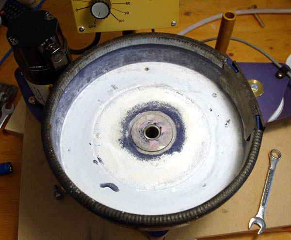
Splash Pan and Spindle Housing

Here is a close-up of the Spindle Housing where it joins the Splash Pan. I have done nothing to it at this point except remove the Platen and Spindle.
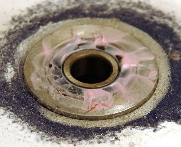
Omni Spindle Housing Splash Pan flaw close-up

The pink smears are some sort of lithium grease. The webby-bits are lint and dust from the air, and the white stuff is ground gem dust.

Omni Bearing Design Flaw

There is no lip or any sort of rubber dam/gasket/barrier to prevent water from reaching the bearing or leaking down between the Spindle Housing and Splash Pan.

There is no protection to prevent water from reaching the Bearings.

The Splash Pan has a mild gradient to it, the center being about 1/8″ higher than the edge. But otherwise there is no protection for the Spindle Housing or bearings from water flooding. No rubber o-ring or gasket, not even a layer of grease to prevent water from flowing between the Splash Pan and the Spindle Housing.
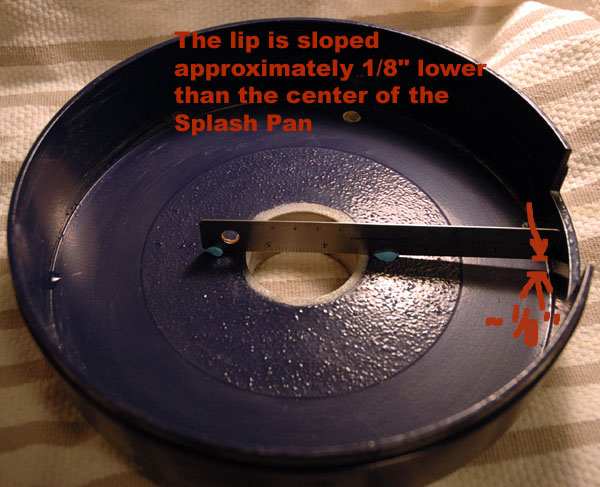
Omni Splash Pan Gradient

If you use a lot of water (when roughing for example) or your hose isn’t draining properly, you WILL flood your Spindle Housing and Bearings. There is nothing to prevent water from flowing there. Eventually, you WILL flood your Bearings and Spindle Housing. PERIOD.

Here is the Spindle Housing removed from the Splash Pan. As I stated above, I have cut 3 stones on the machine since it was returned to me from the factory.
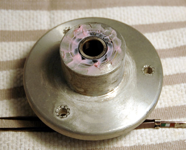
Omni Spindle House Corrosion Close-up 1

Note the rock powder and corrosion stains from water leaking between the Splash Pan and the Spindle Housing. This is a machined part – it should be completely smooth and shiny, not pitted and rough.

Here’s a side view close-up of the Spindle Housing. Notice how quickly the corrosion has started to pit the machined part.
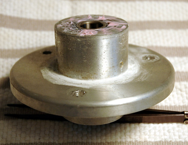
Omni Spindle House Corrosion Close-up 2

Here’s a close-up of the Splash Pan where it contacts the Spindle Housing. Notice the corrosion here too.
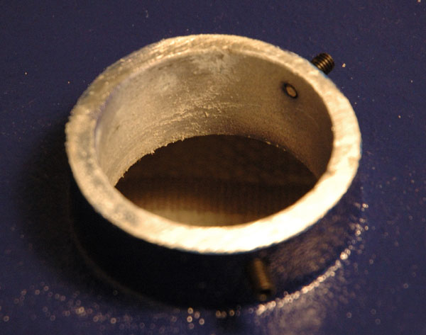
Omni Splash Pan Corrosion close-up

This is due to the two parts – the Spindle Housing and Splash Pan – being dissimilar metals. Add in a bit of water and you end up with galvanic corrosion occurring, causing the pitting.

Left long enough, this will destroy the Spindle Housing and Splash Pan. At very least, it will fuse the two together with corrosion. THIS SHOULD *NEVER* HAPPEN IN A GOOD DESIGN.

IS THIS THE SORT OF DESIGN YOU EXPECT FROM A PRECISION INSTRUMENT COSTING $2200?

There obviously was a reasonable amount of water that made it from my Splash Pan down the Spindle Housing to the Base, though not enough to drip into the bottom cover and wet my work table and alert me of the problem. You can see the beginning of rust and corrosion on the three set screws in this photo.
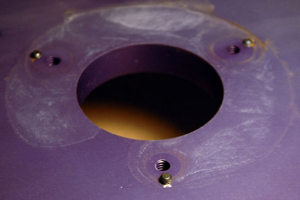
Omni Base Plate Corrosion Marks

There should at least be a waterproof collar around the hole the Spindle Housing enters to prevent any water from making its way between the parts.

Suggested fixes (see the Omni Modifications section for details):

  • Put a bit of silicon rubber sealer between the Splash Pan and the Spindle Housing to seal the gap (this won’t stop water from getting into the bearing if water gets this far)
  • Put a bead of silicon rubber around the Splash Pan hole, say about 1″ from the edge. This will give the Platen enough clearance to not rub against it
  • Create a new Splash Pan. I will be working on this in the coming weeks. I am thinking of a 4″ ID PVC tubing glued inside a 10″-11″ plastic container of some description.

Remember, I have only cut 3 stones so far. What would this look like after a year of cutting?

More important: Is this owner abuse of the machine? Or is it a “mechanical fault detrimental to the operation of the machine for which the manufacturer is responsible”?

Posted in Flooded Bearings | Tagged , , , , , , | 6 Comments

Omni Faceting Machine Design Flaws

After starting to disassemble my Omni-E Faceting Machine, I discovered several things which cause me grave concern.

This section will discuss the various design flaws and poor craftsmanship that I’ve uncovered on my Omni.

In short, there are three significant issues I have discovered on my Omni. You may draw your own conclusions as to whether these are just my machine or systemic to all Omni Faceting Machines.

  1. Flooded Spindle Bearings/Leaks/Corrosion – A critical design flaw that Jersey Instruments is blaming on owner abuse and thus charging for warranty work.
  2. Inaccurate Transfer Jig – Another critical design flaw that means when you transfer your stone to another dop you’ll likely be well out of alignment.
  3. Omni Faceting Machine Swing Arm Flex – Due to poor choice of materials and improper tightening of the Swing Arm at the factory, the arm flexes with even gentle hand pressure.
Posted in Omni Design Flaws | Tagged , , , , , | Leave a comment

Omni Bottom Cover and Pulley Assembly

In order to disassemble any of the Platen, Spindle, Splash Pan, or Bearings you will first need to remove the bottom pulley cover and the Spindle Pulley.

Use a screwdriver to remove the two screws holding the bottom pulley cover in place.

Bottom of the Omni with the Pulley Cover removed.

Here is a photo of the bottom of the Omni with the pulley cover removed, showing the Motor and Spindle Pulleys with the drive belts.

Carefully remove the drive belts from the pulleys and set aside.

To remove the Spindle Pulley you need to use a 1/8″ Allen key. Insert it into the set screw (the black screw) and turn counter-clockwise. It may be quite tight and take a bit of force to loosen.

Once it has been loosened you will be able to easily slide the Pulley from the Spindle. (You may want to check out the Pulley Quality Control page)

Posted in Belt Cover & Spindle Pulley | Tagged , , , | Leave a comment

Omni Disassembly First Steps

This section details how to disassemble the various parts of the Omni Faceting Machine.

Note: Disassembling your machine will void your warranty. I am in no way responsible for any eventualities should you decide to disassemble your machine.

First steps:

  1. Remove and drain the water drip tank. Drain all water from the Splash Pan and dry it. DO NOT POUR WATER INTO THE SPLASH PAN TO WASH IT OUT! YOU WILL FLOOD YOUR BEARINGS! Remove the drain hose.
  2. Unplug the electrical cord.
  3. Disconnect the Encoder on the Faceting Head. You will need to use a Phillips screwdriver to remove the cable hold-downs on the Faceting Head so you can remove the wires connecting the Encoder to the Control Box.
    Encoder Cable Connector and Cable holder

    Encoder Cable Holder under Quill

  4. Carefully lift the Faceting Head off the Mast. Be careful as there is a ball bearing at the top of the mast which may go rolling off into the distance. Place the Faceting Head down somewhere safe, where it can’t fall or have things dropped on it. Put the ball bearing somewhere safe.
    Ball Bearing at the top of the Mast

You now are ready to start disassembling the rest of the Omni.

Posted in Disassembly First Steps | Tagged , , , | Leave a comment

Pulley Quality Control

As I was taking Platen and Spindle out of my Omni, I had to remove the Spindle Pulley underneath the machine. What you see here are some photos of the Spindle Pulley quality.

Omni Pulley Quality Image 1

So what do you think of the quality of the Omni Spindle Pulley? This is a top-view of the pulley after I took it off the Spindle.

Omni Pulley Quality Image 2

A close-up view of the Spindle Pulley top surface. One person asked me if it was a salt build-up on the pulley due to me flooding the machine. No, it is not.

Omni Pulley Quality Image 3

Even closer pic. This is not something on the surface; these are voids and pits left behind from a faulty casting of the piece that was machined to create the part. They are anywhere from just below the machined surface to a few millimeters deep in the biggest black void.

Given that this sucker can be spun at up to 1000 RPM, those voids probably are making the pulley unbalanced, causing at least some of the high-speed vibrations.

I’m concerned that this is not viewed as a quality problem by Jersey Instruments. In my opinion this is a sub-standard or defective part that never should have been installed in the first place.

What causes me more concern is that I sent my machine back for servicing and this part had to be removed at the factory to replace the bearings. This means that they saw the condition of this part and just put it back on.

It’s a beautiful Catch-22 – there’s a defective part, but the only way you’d discover it is by doing something which would void your warranty… so they don’t have to fix it. And if they did, you’d re-void your warranty if you opened it up to check it again.

Not to belabor the point, but is this the indication of a well-built, quality machine?

Posted in Omni Quality? | Tagged , , , , | 1 Comment