Click on the These Titles

If you are having problems finding the photos, you need to click on the the titles of the posts… the software I’m using is meant for blogging which means it won’t show the full page of the item until you click on the title of the summary.

And if you’re trying to leave comments, you first need to register and sign in. Then you should see the Comment box at the bottom of each post where you can type your comments and click on the Submit Comment button.

If you’re having trouble creating an account, please email me allan(at)omnifaceter.net and I’ll manually create an account for you.

Thanks for the tremendous response from everyone, and the words of encouragement!

-Allan

Posted in Blog | Leave a comment

Modifications I’ve Done to My Omni

In this section I’ll be posting pictures of modifications I’ve done to my Omni Faceting Machine.

At present I’m concentrating on how to improve the reliability of the machine and correct some of the glaring design flaws.

The first two modifications have been to Protect the Spindle Bearings and to Reduce the Platen diameter.

Later I will probably look to add additional components in order to improve the accuracy and repeatability of the Omni – keeping the alignment in good order and making it easier to use.

Next on my list is to create a better Splash Pan (wider and isolated from the Spindle Housing and Bearings to absolutely prevent flooding.

After that I’m going to get a new Platen and Spindle machined, with a proper left-hand threaded nut to hold the laps down with. And also to get a better 45 degree angle dop made.

Longer-term I’m going to build my own base – the warped base plate is probably contributing to the Mast alignment problem and I don’t trust it any more. Getting rid of the warped base plate will eliminate the frustration of trying to find a reference point to align things from.

I’ll post photos and commentary as I go. I will also post recommended suppliers and machinists if I find someone I like and get good quality work done.

Posted in Omni Modifications | Tagged , , , | Leave a comment

Omni Faceting Head Details

Here are some photos of the Omni Faceting Head.

This first view shows the Faceting Head with the black Encoder. The large blue knob is the Coarse Height Adjustment which moves the head up and down the outer sleeve with a rack-and-pinion design. The small gold knob in the middle is the height adjustment locking knob. The gold knob at the top of the Mast is the Fine Height Adjustment – it has about 1/2″ of adjustment ability.

Omni Faceting Head Encoder Side view

This is the other side of the Omni Faceting Head showing the Coarse Angle Adjustment knob (large blue knob) and the Cheater (small gold knob near the bottom right of the head). Notice the Fine Angle Adjustment system – the finely-threaded screw that contacts the projection just below it.

Omni Faceting Head Angle Lock Side view

A more detailed view of the Fine Angle Adjustment system.

Omni Faceting Head Fine Angle Adjuster detail

Here is a face-on view of the Quill and Index Wheel. The Index Wheel can be changed by undoing the two screws on the face. Note the orange ball – it’s the tip of the Cheater and Free-Wheel pin. It’s engaged at the 96 Index right now. You can see the Cheater knob quite clearly.

Omni Faceting Head Quill and Index Wheel detail

And finally, here’s a view of the rack-and-pinion side of the sleeve.

Omni Faceting Head Rack-and-Pinion system view

Posted in Omni Faceting Head | Tagged | Leave a comment

Modifying The Omni Faceting Machine

In this section I’ll be posting different modifications that I have done to my Omni.

These modifications will definitely void your Omni’s warranty (if you care). But by now you’ve probably realized that and I’m not going to mention it again.

If you have any modifications that you have done to your machine that you’d like to share, please contact me and I’ll put them up here.

-Allan

Posted in Blog | Tagged , , | Leave a comment

It’s Live!

Well, after quite a few hours of fiddling and some last-minute technical trouble-shooting of the web hosting, the omnifaceter.net website is finally up and running!

Thank-you to those who have seen and help guided this site during is conception and development phase. Without your feedback and advice this site would not be nearly as complete.

For everyone else – please read and enjoy. I hope that the information and photos I’ve posted here can help others resolve any problems they’ve been having with their Omni Faceting Machine. I had hoped that such a site wouldn’t be necessary, but my personal experience and discussions with other Omni owners showed otherwise.

-Allan

Posted in Blog | Tagged , , | 2 Comments

Aligning the Mast

Disclaimer: performing this procedure may void your warranty. Proceed at your own risk.

Warning: this is a slow and tedious process. If you are not mechanically inclined, think wrenches can be used as hammers or have a short fuse — do not attempt to adjust the alignment yourself. You’ll probably make it worse than it was.

You probably don’t have to strip down your Omni to the point I did for this process, but you will have to remove the Omni Spindle Housing so you have access to the Base Plate.

Finding a Reference Point

The hardest part of aligning the Mast of the Omni is trying to find something flat to reference to. As mentioned in other posts, my Base Plate is warped and can’t be trusted to align the Mast to. The real problem was that nothing seemed to be consistent enough to use as the tie-back point where everything should line up.

I compromised by arbitrarily deciding that I wanted a flat surface (not a point) to measure the Mast alignment to. This was because I found it easier to detect and locate the worst tilt by swinging a dop over a surface, rather than watching it over a single point. Depending on your spacial skills, you may find a simpler and easier way to align your Mast than I’m outlining here.

Tools and Materials

You’re going to need your flattest lap, a 3/16″ Allen key, a 3/32″ Allen key, various pieces of shim metal (I used brass shim stock from a sample pack I bought at Lee Valley Tools), a marker and a lot of patience.

My Mast appeared to be tilting away from the lap, so that the Quill traced an arc that was higher in the center of the lap than at the edges. You can also adjust for the other situation of an inverted arc where the Quill is lower at the center by starting at the lowest point of the lap.

I took the lap (an old ceramic lap that I know is flat) and centered it on the Base Plate over the Platen Tilt Adjustment Allen Screws. I put a dop in the Quill and adjusted the angle of the Faceting Head to about 40 degrees.

I moved my Swing Arm in so the tip of the dop was at the 6 o’clock position over the lap. I tightened the Swing Arm so it wouldn’t move easily and marked it so I knew exactly where the Swing Arm was positioned. I then lowered the dop until it barely touched the edge of the lap.

I swung the Quill so the dop was now at the other edge of the lap at about 1 o’clock. In my case that edge was higher than the 6 o’clock position, so I raised the Faceting Head until the tip of the dop barely touched the lap surface.

After all that, I used the Platen Tilt Allen Screws to adjust the angle of my ceramic lap until I had the tip of the dop barely touching the surface of the lap at both the 6 o’clock and 1 o’clock positions. The tricky part is not disturbing the position of the lap after this – I ended up using a bit of tape.

In these photos you can see how I’m doing this. I’ve chosen to use a stone glued on the dop because I found I could hear the scrape of the stone on the lap better than the dop.

Omni Mast Alignment Image 1

Omni Mast Alignment Image 2

Now put a ink mark on the Mast, Mast Bushing and Swing Arm so you know where all the parts were before you started. The photo doesn’t show the mark on the Swing Arm that lines up with the marking on the far side of the Mast and Bushing.

Omni Mast Alignment Mast Bushing Closeup

Finding the Worst Mast Tilt

Using the 3/16″ Allen key loosen the Mast Bolt. Be careful to keep both Mast and Bushing in alignment. Rotate the Mast and Mast Bushing together about 15 or 20 degrees. Tighten the Mast Bolt.

Now check the height of the tip of the dop over your lap. Is it worse or better?

  • If worse, keep turning in the same direction you started.
  • If better, reverse the direction you’re rotating the Mast and Bushing.

Adjust the height until the dop is barely touching the lap again. Repeat these steps until you’ve made the Mast have the worst arc possible. This took me about 20 minutes of going back and forth.

Congratulations! You now know that the Mast is tilting back pretty much directly in line with the center of the lap.

Mark the Mast, Bushing and Swing Arm on the back side of the Swing Arm in line with the center hole of the lap. This tells you where you need to insert the shims.

Adjusting the Mast Tilt

Now you need to try to figure out how much shim metal to put under the Bushing.

Loosen the Mast Bolt and rotate the Mast and Bushing 90 degrees clockwise. Tighten the bolt. The Mast is now tilting back towards the 6 o’clock position.

Adjust the Facet Head height so that the tip of the dop just touches the surface of the lap at the 6 o’clock position. This should be pretty close to being the height the dop tip needs to be when we’re finished our adjustment.

Loosen the Mast Bolt and rotate the Mast and Bushing 90 degrees counter-clockwise so it’s back in the worst orientation. Tighten the bolt. Swing the Quill so the tip of the dop is above the 6 o’clock position on the lap. When we’re done with the adjustment, the tip should just be touching the lap.

Now cut some arrow-shaped pieces of shim metal. Adjust the Mast tilt by inserting pieces of shim so the point is touching the Mast where you’ve marked the back of the Mast and Bushing. Tighten the Mast Bolt after each additional piece and check the dop position. Once the tip of the dop is touching the lap, you’re almost done. This step took about 10 minutes.

Omni Mast Alignment Brass Shims

Omni Mast Bushing with Shims in place

The last thing to do is a sanity-check. Loosen the Mast Bolt and turn the Mast, Bushing and shims 180 degrees. Tighten the Mast Bolt and check the height of the dop tip at the 6 o’clock position. You should be pretty close to just touching the lap. If you’ve hit it perfectly, congratulations! I wasn’t able to get it perfectly accurate but pretty darned close. If not, play around with the amount of shim you are using until you are satisfied. I spent another 5-10 minutes double-checking.

Tighten the Mast Bolt well and you’re ready to Align the Platen.

Posted in Aligning the Mast | Tagged , | Leave a comment

Aligning the Platen

Disclaimer: performing this procedure may void your warranty. Proceed at your own risk.

Warning: this is a slow and tedious process. If you are not mechanically inclined, think wrenches can be used as hammers or have a short fuse — do not attempt to adjust the alignment yourself. You’ll probably make it worse than it was.

Before you begin to attempt aligning the Platen of your Omni, ensure your Mast is perpendicular to the Swing Arm.

The simplest way of doing this is setting the angle of the Faceting Head to around 70 degrees, so it’s almost horizontal. Put the large dop in the Quill and the flattest lap you own on the Platen. In my case I have an old ceramic lap that I used on my MDR faceting machine, which I know is as flat as I can hope to get.

Adjust the Swing Arm and Faceting Head so the tip of the dop just barely touches the surface of the lap at the 6 o’clock position (closest to the user).

Swing the dop slowly across the surface of the lap and observe closely the path the tip traces. If the tip traces even a slight arc rather than a straight line — that is, it’s either lower at the edges or lower in the middle than the edges — your mast will need alignment.

Test this several times with the Swing Arm in various positions.

For an explanation of what you are looking for, have a look at the Omni Mast Not Aligned page. The arc may be reversed (tip higher at the edges than in the middle) depending on your particular machine.

If you determine your Mast is not straight, check out the Aligning the Mast page.

Once you are sure your Mast is as straight as it can be, proceed with aligning the Platen.

The method for aligning the Platen to the Faceting Head is done by adjusting both the Hold-down Bolts and Allen screws that attach the Spindle Housing to the Omni base plate. Below are some photos showing where these Hold-down Bolts and Allen Screws are.
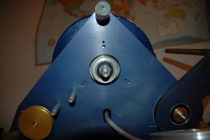
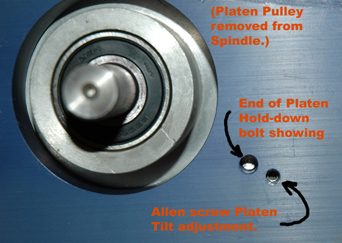
Bottom of the Omni with the Pulley Cover removed.

Omni Platen Adjustment Screws Bottom View

Here are some instructions I received from the owner of Jersey Instruments:

“Look under the splash bowl. You will see three mounting bolts. These bolts control the alignment of the platen. Using a 7/16 wrench, you can adjust the bolts to align the machine. Do not loosen or tighten the bolts more than 1/2 turn. There are set screws under the base plate which must be adjusted to tension the spindle housing. They are accessed by removing the spindle pulley. For minor adjustments you need not adjust the set screws.”

Here is a side-view of those Hold-down Bolts and Allen Screws. Note the rubber o-ring showing in the picture.
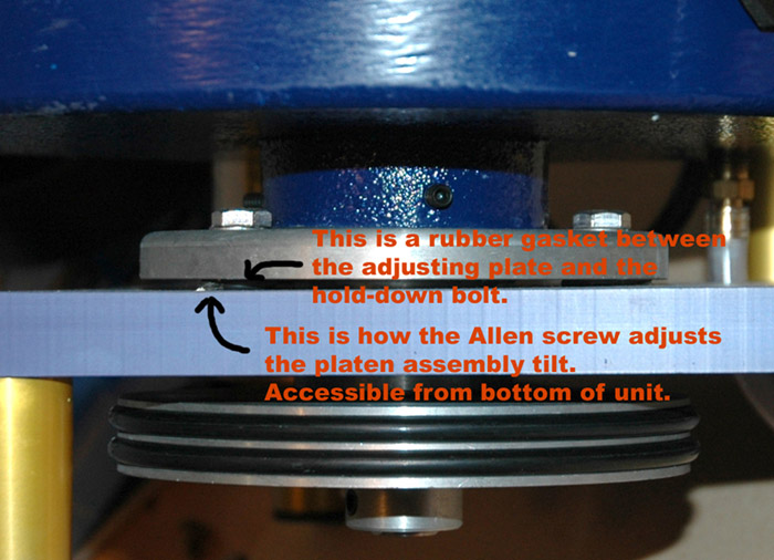
Omni Platen Tilt Adjustment Screws View 2

My experience is that those hold-down bolts are very tight and you need to be careful in tensioning them more than they already are. In fact, I don’t recommend following the above instructions at all. In my opinion it’s too easy to over-tighten the Hold-down Bolts and damage something.

I ended up loosening the Hold-down Bolts (7/16″ wrench) and removing the Spindle Housing from the Base Plate. I discarded the rubber o-rings as they were torn and I could see no obvious function they performed. After cleaning the whole area of swarf and corrosion and removing and greasing the Hold-down Bolts and Allen Screws, I set the Spindle Housing back on top of the Allen Screws and put the Hold-down Bolts in finger-tight. Make sure you orient the Spindle Housing correctly – with the Splash Pan opening pointed in the right direction.

Note: For my alignment process the Spindle Pulley will not be attached to the Spindle.

Important: With a dop in the Quill lower it to barely touch the Platen. Rotate your Platen to find out where the high spot is, and mark it with a Jiffy marker or something. You will want to base all your measurements from this same point on the Platen for each of the positions listed.

With a dop in the Quill I then positioned the tip of the dop just touching the mark on the Platen right above the 6 o’clock Hold-down Bolt.

I then moved the Swing Arm and Quill so the tip of the dop was above the 2 o’clock Hold-down Bolt, rotating the Platen so the tip of the dop is on the marked spot.

Using a 3/32″ Allen key I adjusted the 2 o’clock Allen Screw under the base plate to get the Platen to just barely touch the tip of the dop.

I repeated the process at the 10 o’clock Hold-down Bolt, then went back to the 6 o’clock Hold-down Bolt to verify the Platen was still just touching the tip of the dop. Be sure to rotate the Platen so the high mark is under the dop tip each time. I repeated this process a couple of times.

You can see photos of the process I used below. I used the D-dop and my newly-reduced Platen in these photos. I left off the Splash Pan for clarity. The pictures are in order for the 6, 2, and 10 o’clock Hold-down Bolt positions.
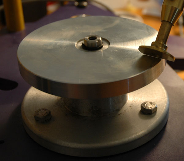
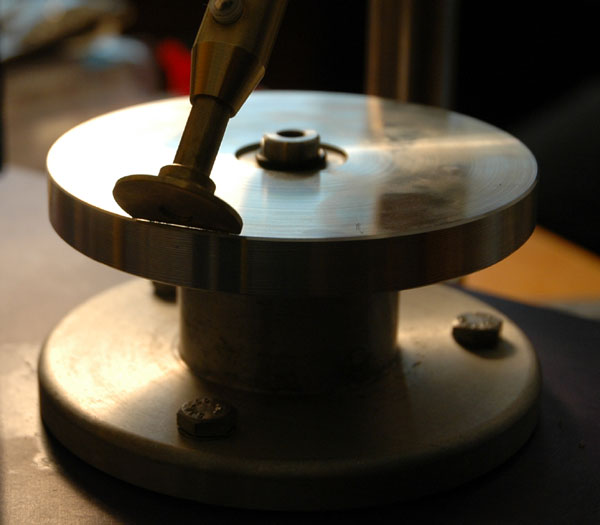
Omni Platen Tilt Adjustment View 1

Omni Platen Tilt Adjustment View 2

Omni Platen Tilt Adjustment View 3

Seeing these photos makes me want to wipe the grease and fingerprints from the Platen!

Now go around and carefully tighten the Hold-down Bolts in turn checking the alignment with the dop as described above for each one. Don’t forget to rotate the Platen so the mark is under the dop tip each time.

I tightened each Hold-down Bolt about 1/8 turn at a time, going round and round until they were tight but not feeling forced. As you tighten the Hold-down Bolts you will see a space open up between the tip of the dop and the Platen. Adjust the height of the Faceting Head after each round of tightening so the tip of the dop barely touches the Platen surface.

Now test the alignment by putting your flattest lap on the Platen and putting the D-dop into the Quill. Adjust the angle and height of the Faceting Head so the edge of the D-dop barely touches the lap surface. Use the Cheater to make sure it’s as level as you can get it. And now sweep the dop across the lap with the Swing Arm in various positions. If you’ve adjusted the Mast and the Platen well, you should see the dop sweep across the lap without any arc or change in height. It won’t be perfect but it should be a heck of a lot better than when you started.

Don’t forget to re-attach the Spindle Pulley and put the drive belts and cover on etc.

Not having spent a lot of time cutting recently, I don’t know how long this alignment will hold before having to go through it again. If you try it out, please leave some comments as to your experience.

Posted in Aligning the Platen | Tagged , | Leave a comment

Reducing the Omni Platen Diameter

This is another modification I made to my Omni. I find the original 5-3/4″ Platen diameter to be too wide, so there isn’t enough friction between the Platen and the lap. If I turn the speed control up quickly, the lap often will skid on the Platen as it comes up to speed. This will then loosen the screw holding the lap down which makes the problem worse.

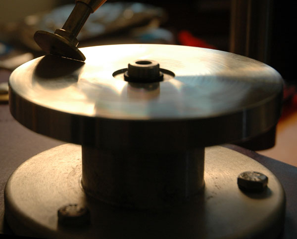
Here is the modified Platen. I had it cut down to 4-1/4″ diameter which has eliminated the skidding lap problem.

Modified Platen - reduced to 4-1/4

This is what the it looks like when installed in the Omni.

Omni with Modified Platen

Posted in Smaller Platen | Tagged , | Leave a comment

Protecting Your Omni Spindle Bearings

Here is a simple modification I did to my Splash Pan to help protect the Spindle Bearings and other components from water and corrosion.

After disassembling the Platen and Spindle and Splash Pan I washed out all the rock dust and grease. I then put a bead of silicon rubber around the center of the Splash Pan (the stuff I have is black but any will do). This bead is about 1/4″ high, and should prevent any water from inadvertently getting down into the Spindle Bearings or between the Splash Pan and Spindle Housing.

Modified Splash Pan with Silicon Rubber Dam 1

Wait for the rubber to dry before replacing your Platen and Spindle.

Be careful that your silicon dam is not too high – if it is, it will rub against the underside of your Platen when you re-install it.

Modified Splash Pan with Silicon Rubber Dam 2

You can also see that I’ve smeared silicon grease into the gap between the Spindle Housing and Splash Pan. This will prevent any water that happens to get splashed over the rubber dam from corroding the Splash Pan and Spindle Housing any more.

This will guard against reasonable amounts of water in the Splash Pan – up to 1/4″ deep. However it’s still not adequate in my regard and I will be making my own Splash Pan (wider in diameter) out of some plastic later.

Posted in Bearing Protection | Tagged , , , , | 1 Comment

Warped Omni Base Plate

On every other machine the flatness of the base plate is critical. These machines need it to be precision-ground so that the mast will remain in the same orientation as it slides back and forth along the base plate.

For the Omni, this is not as big an issue as the Faceting Head and Mast are mounted on the Swing Arm instead. It still is important though, as the Swing Arm and Base Plate must remain in alignment as the Swing Arm moves in and out.

It also becomes an issue when you want to align the Mast perpendicular to the Base Plate, or if you wanted to use a dial indicator to align the Platen to the Base Plate. Without something accurate to measure against, you have no clue what part is oriented correctly or not.

I discovered the problem when I tried to adjust the Platen Tilt using a dial indicator attached to a base sitting on the Base Plate. After a few minutes I stopped as it was obvious the Platen was getting completely mis-aligned by this method. I then took a machined piece of tool steel and placed that on the Base Plate and measured it with the dial indicator. After moving both the block of steel and the dial indicator base I realized the Base Plate was too warped to use for aligning the Platen.

Here are a series of photos I took holding a metal straight edge against various parts of my Omni’s Base Plate. If it were flat, you wouldn’t see even a sliver of light between the edge and the Base Plate. Or you would see a very thin but even line of light along the straight edge.

As you can see for yourself, the Base Plate warp is pretty severe in some places and not consistent across the surface.

Omni Base Plate Warping image 1

Warped Base Plate - View from Motor Mount Towards Swing Arm Mount

Omni Base Plate Warping image 2

Warped Base Plate - View Across Back to Swing Arm Mounting Point

Omni Base Plate Warping image 3

Warped Base Plate - Along the Back of the Base Plate

Omni Base Plate Warping image 4

Warped Base Plate - Along the Middle of the Base Plate

The Base Plate is about 5/8″ thick, which should be more than sturdy enough to withstand the weight of any components mounted on it. And it’s far too thick to be warped by using the machine. To warp or bend this thickness of metal you’d leave behind obvious dents.

My conclusion is that the Base Plate was never machined flat in the first place. Which again calls into question the workmanship and quality of the Omni Faceting Machine construction.

How does this affect the machine? It makes it almost impossible to align the components as there is nothing accurate to measure against. Trying to find something to Align the Mast to was an interesting challenge.

Posted in Omni Quality?, Warped Base Plate | Tagged , , , | 2 Comments